DAMASK — Examples
Effect of the orientation of a single grain on the distribution of stress and strain in neighboring grains
General idea:
The influence of the crystallographic orientation of a single grain on the equivalent stress and strain in its neighboring grains is analyzed. For that, a 3D microstructure, discretized into 128 × 128 × 128 grid points, is constructed from a VORONOI tessellation with 50 randomly placed seed points. To change the local mechanical response, a central grain is selected and its initial crystallographic orientation (give as Euler angles) is chosen as ϕ1=0, Φ=0, ϕ2=0 in the reference microstructure and as ϕ1≠0, Φ=0, ϕ2=0, ϕ1=10, 20, 30, 40, 50, 60, 70, 80 and 90 degrees in the microstructure variants.The mechanical response of the reference microstructure is compared to the modified microstructures. For that the microstructures are deformed using the Spectral solver and the differences in equivalent stress and strain are calculated between reference simulation and modified microstructure. A detailed description of this work is presented in the following.
Pre processing:
Microstructure creation
First, 50 random seeds are randomly placed within a three-dimensional cube of [0.0, 0.0, 0.0]—[1.0, 1.0, 1.0] by calling seeds_fromRandom (including including parameter N for number of grains and g for the resolution) in DAMASK.> seeds_fromRandom -N 50 -g 128 128 128 > orientation.seedsgeom_fromVoronoiTessellation enables to create a microstructure with random orientations fron an existing the created seed file. Every grid point is assigned to a grain identification number with
> geom_fromVoronoiTessellation < orientation.seeds > 50grains128x128x128_00.geomThe notation "_00" here in the output file stands for the value of ϕ1 of the considered grain. The result is a geometry specification for the spectral solver with the <texture> and <microstructure> parts of the material.config in the header. To visualize the geometry in DAMASK, a rectilinear grid can be produced by using the geom_check script.
> geom_check 50grains128x128x128_00.geom

| ||
| Figure 1: 3D microstructure containing 50 grains generated by using a Voronoi tessellation and discretized into a grid of 128 × 128 × 128 points. |
Modification of the original microstructure by rotation of a central grain
The created file 50grains128x128x128_00.vtr is visualized in paraview and the grain ID of a grain located close to the center is identified with help of the threshold filter. Its crystallographic orientation in theFigure 1 shows the geometry of the generated microstructure. Figure 2 shows the different crystallographic orientations of the central grain starting with the reference structure followed by modified microstructures for ϕ1 = 10, 20, ..., 90 degrees.
| Figure 2: IPF of the central grain for the reference microstructure and the variants |
Summary: Files needed for running the simulation
- Load definition: Contains all information about the loadcase. Here, the applied strain rate and the stress conditions are shown in tensor form. Components denoted with ``*'' are prescribed with complementary conditions. In this simulation the material is strained in x-direction.
> fdot 1.0e-3 0 0 0 * 0 0 0 * stress * * * * 0 * * * 0 time 10 incs 40 freq 4 > fdot 1.0e-3 0 0 0 * 0 0 0 * stress * * * * 0 * * * 0 time 60 incs 60 - Geometry defintion: The geometry defintion as obtained from seeds_fromRandom and geom_fromVoronoiTessellation.
- Microstructure configuration and Texture configuration are taken from the header of the generated geometry file (including the changes to the Euler angles of the central grain).
- Homogenization configuration In the presented simulations the spectral solver is used with a dummy homogenization of type none.
- Crystallite configuration In this file the output at the crystallite level is requested. For this simulation the parameters texture, stress, strain gradient, and Euler angles are considered.
- Phase configuration Contains all information about the deformation behavior of the material, examples are found in the examples folder of DAMASK.
Running the simulation:
After set up the required files for pre processing, the simulation process is started by applying the load to the periodic volume element. DAMASK_spectral is invoked with the arguments giving microstructure definition and the load file.> DAMASK_spectral --geometry 50grains128x128x128_00.geom --load tension.load00 is the notation for ϕ1 = 0 (exemplary for orientation ϕ1 = 0, ϕ = 0, ϕ2 = 0). The output data of the simulation is written into spectral.out files.
Post processing:
Processing results of the individual simulations
The first post processing step is the conversion of required data from the binary *.spectralOut file into an ASCIItable with postResults:> postResults 50grains128x128x128_00_tensionX.spectralOut \ > --cr fp,f,p,orientation,grainrotation,texture \ > --co shearrate_slip,shearrate_slip \ > --separation x,y,z \ > --increments --range 60 60 1 --splitwhere
--split indicates splitting of the results per time increment, --separation x,y,z separates the data spatially (instead of averaging over the whole volume), --increments turns on incremental counting and --range 60 60 1 selects the last increment written out.
To derive further quantities from these basic results, other tools are included in DAMASK.
The commands addStrainTensors that appends to the ASCIItable strain columns derived from the given stretches and addMises for the equivalent values of stress and strain are important for this simulation.
> addStrainTensors -0 -v 50grains128x128x128_00_tensionX_inc60.txt
> addCauchy 50grains128x128x128_00_tensionX_inc60.txt
> addMises -e 'ln(V)' -s Cauchy 50grains128x128x128_00_tensionX_inc60.txt
The labels of the variables in all ASCIItables are the same, hence they need to be renamed before the data is merged in order to compute the differences. reLabel enables to rename a scalar, vectorial, or tensorial data in the ASCIItable.
> reLabel -l fp,f,p,'ln(V)',Cauchy,'Mises(ln(V))','Mises(Cauchy)',texture -s fp-00,f-00,p-00,'ln(V)-00',Cauchy-00,'Mises(ln(V))-00','Mises(Cauchy)-00',texture-00 50grains128x128x128_00_tensionX_inc60.txt
Calculations of the differences in equivalent stress and strain distributions of the neighboring grains due to the rotation of the central grain
After creating an ASCIItable, the next step is to show the influence of the orientation of a single grain on its neighboring grains. To achieve this effect, differences in stress and strain states are calculated for different orientations. First, to every ASCIItable with ϕ1 > 0 the original table for ϕ1 = 0 is appended, as shown here (exemplarily for ϕ1 = 0 and ϕ1 = 10):> paste -d ' ' 50grains128x128x128_10_tensionX_inc60.txt 50grains128x128x128_00_tensionX_inc60.txt >temp.txt > mv temp.txt 50grains128x128x128_10_tensionX_inc60.txt128 stands for the resolution, 60 for the increment, 00 and 10 for the values of ϕ1 respectively. To append further columns to an existing table and perform calculation, addCalculation is used. Reference orientation is the orientation ϕ1 = 0, ϕ = 0, ϕ2 = 0 for central grain 5. For varying orientations (ϕ1 = 0 is increased) variations in equivalent stress and strain can be observed. Here the code for the differences in stress and strain is shown exemplary for the orientation of ϕ1=0 and ϕ1=10 degrees.
> addCalculation -l "Delta(Cauchy)","Delta(ln(V))","Delta(Mises(Cauchy))","Delta(Mises(ln(V)))"
-f  "Cauchy-00#-#Cauchy-10#","#ln(V)-00#-#ln(V)-10#","#Mises(Cauchy)-00#-#Mises(Cauchy)-10#","#Mises(ln(V))-00#-#Mises(ln(V))-10#" 50grains128x128x128_00_tensionX_inc60.txt
The last operation is the visualization of the results, in particular the calculated differences. This can be done using vtk_rectilinearGrid and vtk_addRectilinearGridData as outlined in Generate a file for visualization. These files can be visualized in programs such as ParaView or visit.
Results
Differences in equivalent strain and stress of neighboring grains in plane for different orientations of a central grain
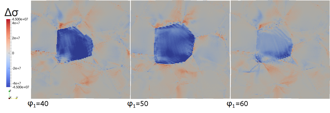
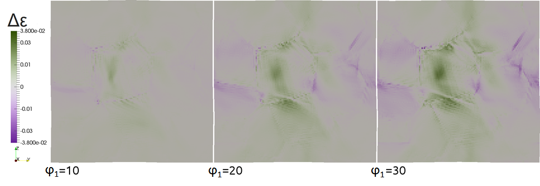
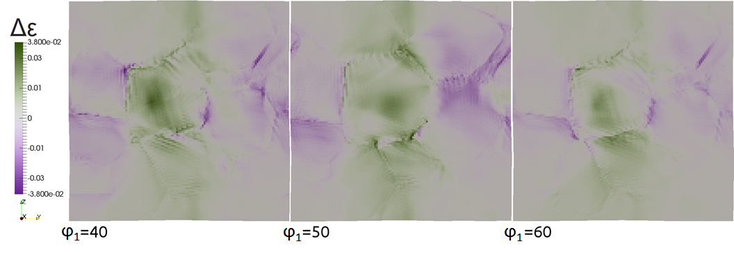
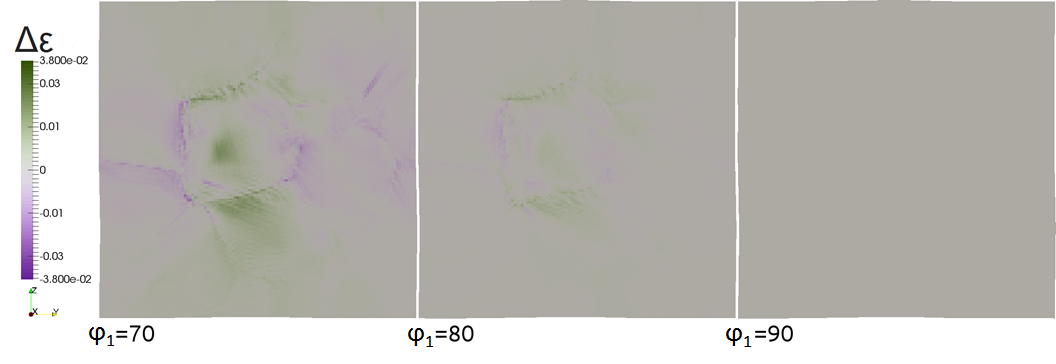
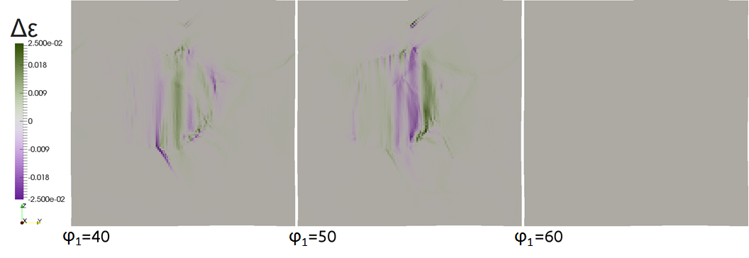
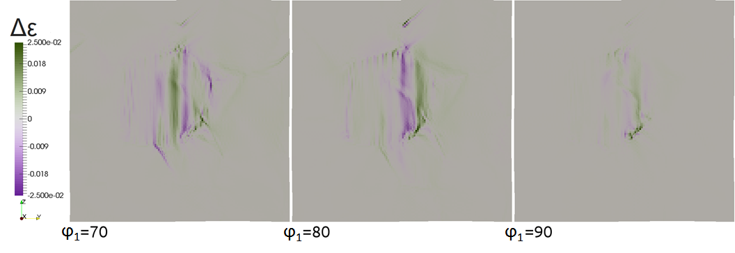
The first sequence of results in Figure 3 shows the local influence of the orientation of one grain on the distribution of stress on the neighboring grains for variations of ϕ1 in plane. The variations are presented in steps of 10 degrees for ϕ1. The magnitude and long-range spread of local stress change significantly with continuing rotation. In terms of stress, red-colored regions indicate hard grains which are not well aligned to the applied loadcase and blue colored regions soft orientations. Grey color indicates that the orientation of the grain has no local effect on the stress distribution. The rotated grain is clearly visible by its soft orientation, while red stress lines are arranged close to grain boundaries at its neighbors. The rotated grain reaches better aligned orientations to the applied load and then the average stress drops to zero with ϕ1=90 degrees due to the symmetry of slip families in cubic crystals. The second sequence in Figure 4 shows the equivalent results for differences in strain dependent on the orientation. For strain, green colored regions undergo low strain, while violet regions exhibit large deformation. Large strained regions are located on and close to the rotated grain and arranged in bands reaching a maximum for a better aligned orientation. Highly contracted regions are located at neighboring grains close to the rotated grain. Grey regions do not show any dependence of the orientation of the central grain. Differences in equivalent strain are arranged in bands and not restricted by grain boundaries. They can be observed not only on the closest neighbors, but decrease exponentially over distance away from the rotated grain. 3D development of differences in equivalent strain and stress of neighbor grains for different orientations of a central grain. Video 2 shows the spatial development of the location for differences in stress distribution with respect of a central grain for varying orientations. The differences illustrated in this video are filtered. Only big deviations are visible representing the locations which are mainly effected by the orientation of the central grain. As seen in the previous results, stress differences can be observed in the 3D cell changing with different orientations of the central grain. After reaching strong variations for φ1=40 and φ1=50, for 90 degrees no differences can be observed as explained before. Differences in stress are arranged in lines mainly at triple junctions and grain boundaries. Video 3 shows the equivalent spatial development of local differences in strain distribution on the surrounding microstructure. In the 3D cell only big strain differences are shown, while small differences are filtered. As seen for stress, strain differences increase first with changing orientation and decrease then with increasing ϕ1. This video verifies the previous results regarding for ϕ1=90 degrees no differences can be observed due to cubic slip system geometry. In comparison to differences in stress, strain variations are also located close to triple junctions and grain boundaries, but more clustered.Both videos show that differences in distributions of equivalent stress and strain are widespread over the closest neighboring grains and not just restricted to the grains next to the rotated one. Strong local variations in their magnitude reveal the effect of microstructure on deformation processes in this simulation. These variations strongly depend on the orientation relationship between the rotated grain and its neighbors.
Interpretation
This simulation is implemented to describe quantitatively the change in stress and strain distribution due to different crystallographic orientations of a central grain. The major role of this orientation for plasticity is shown by calculation the local differences in the mechanical response for two simulations with a rotated grain in the microstructure. The distribution of stress and strain during deformation is mainly influenced by the orientation, because the grains alignment to the applied load changes the amount of resulting deformation carried by this grain. This amount consequently changes the mechanical behavior of the closest neighboring grains. For ϕ1 =0 und ϕ1 =90 the rotated grain reaches cube orientation and therefore no influence on differences in stress and strain are observable.- News
- 14 Sep 2020
-
CMCn2020 & DAMASK user meeting to be hosted at Max-Planck-Institut für Eisenforschung(cancelled) - 22 Aug 2020
- Release of first preview version of DAMASK 3
- 19 Feb 2020
- DAMASK made it to the Advanved Engineering Materials Hall of Fame
- 26 Mar 2019
- DREAM.3D 6.5.119
(released 2019/03/22) comes with a DAMASK export filter - 25 Mar 2019
- Release of version v2.0.3
- 21 Jan 2019
- DAMASK overview paper finally published with full citation information available
- 01 Dec 2018
- DAMASK overview paper now online
- 17 Sep 2018
- CMCn2018 & DAMASK user meeting to be hosted at Max-Planck-Institut für Eisenforschung
- 22 May 2018
- Release of version v2.0.2
- 01 Sep 2016
- CMCn2016 & DAMASK user meeting to be hosted at Max-Planck-Institut für Eisenforschung
- 25 Jul 2016
- Release of version v2.0.1
- 08 Mar 2016
- Release of version v2.0.0
- 22 Feb 2016
- New webserver up and running
- 09 Feb 2016
- Migrated code repository from Subversion to GitLab
- 17 Dec 2014
- Release of revision 3813
- 14 May 2014
- Release of revision 3108
- 02 Apr 2014
- Release of revision 3062
- 16 Oct 2013
- Release of revision 2689
- 15 Jul 2013
- Release of revision 2555
- 15 Feb 2013
- Release of revision 2174
- 13 Feb 2013
-
 documentation
- 16 Dec 2012
-
 rendering
- 23 Nov 2012
- Release of revision 1955
- 15 Nov 2012
- Release of revision 1924
- 01 Nov 2012
- Updated sidebar
- 30 Oct 2012
- Significant website updates and content extensions
Ideas, requests, problems regarding DAMASK? Send feedback
§ Imprint § Data Protection

